What are the Key Components of Fire Pump Systems?
A fire pump system consists of various key components that work together to provide water at the required pressure to firefighting systems, such as sprinklers, hose reels, and hydrants. The essential components include:
1. Fire Pump
The heart of the system, responsible for boosting water pressure. Common types include:
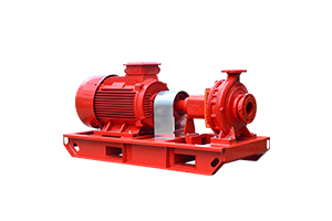
- Electric Fire Pumps: Powered by electricity, they are commonly used in many installations.
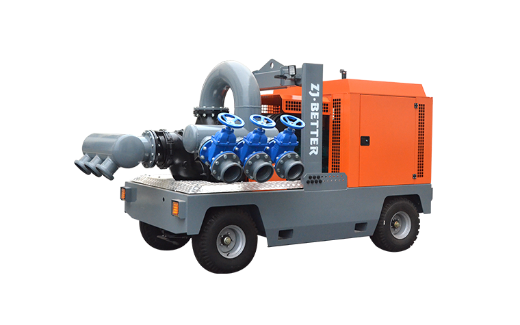
- Diesel Engine Fire Pumps: Used when electric power might be unreliable.
- Jockey Pumps: Maintain system pressure by compensating for small leaks, ensuring the main fire pump doesn't activate unnecessarily.
2. Pump Controllers
Each pump (electric, diesel, or jockey) requires a controller to start, stop, and monitor the pump's operation. Controllers are designed to meet NFPA 20 requirements and vary based on the pump type.
3. Pump Driver (Motor/Engine)
- Electric Motor: Powers electric fire pumps.
- Diesel Engine: Powers diesel fire pumps when electric power is unavailable or unreliable.
4. Fire Pump Relief Valve
This valve helps prevent over-pressurization in the system by releasing water when the pressure exceeds a set limit.
5. Backflow Preventer
Ensures that water flows only in one direction, preventing contaminated water from re-entering the clean water supply.
6. Pressure Relief Valve
Protects the fire pump from damage due to high pressure by releasing excess pressure when needed.
7. Suction and Discharge Piping
- Suction Piping: Supplies water to the fire pump from the water source (e.g., a tank or city water supply).
- Discharge Piping: Delivers water from the pump to the fire protection system.
8. Fire Pump Bypass
This allows water to bypass the pump in case of pump failure or during maintenance, ensuring water is still supplied to the fire protection system.
9. Flow Meter
Used for testing purposes, this device measures the flow rate of the water in the system to ensure the pump is performing as expected.
10. Test Header
Enables the system to be tested under full-flow conditions without discharging water into the protected building.
11. Casing Relief Valve
Installed on the pump casing, this valve releases pressure from the pump to prevent overheating when the pump is running at churn (no flow).
12. Alarm Devices
These include pressure switches, flow switches, and other alarm-initiating devices that notify personnel when the system is activated or if any issues occur.
These components ensure that a fire pump system operates effectively, reliably, and in compliance with standards such as NFPA 20 and UL listing, which are essential in delivering the right pressure during a fire emergency.

.png)
.png)

.png)


