.png)
.png)
.png)
-
 Sep 18, 2023The correct use of fire pumpsFire pumps are a critical component of a fire protection system, and their correct use is essential for effective fire suppression. Here are the key aspects of using fire pumps correctly:View details
 -
Sep 18, 2023The correct use of fire pumpsFire pumps are a critical component of a fire protection system, and their correct use is essential for effective fire suppression. Here are the key aspects of using fire pumps correctly:View details
-
 Sep 15, 2023Precautions for using fire pumpsFire pumps play a critical role in fire protection systems, ensuring a reliable source of water to combat fires. To use fire pumps safely and effectively, it's important to follow specific precautions and guidelines. Here are some key precautions for using fire pumps:
Regular Inspection and Maintenance: Regularly inspect and maintain fire pumps according to manufacturer recommendations and relevant codes and standards. This includes checking for wear and tear, testing control systems, and ensuring all components are in proper working condition.
Qualified Personnel: Only trained and qualified personnel should operate and maintain fire pumps. Make sure that your staff understands the system, its components, and the procedures for starting, stopping, and maintaining the pump.
Proper Documentation: Maintain accurate records of inspections, maintenance activities, and tests. This documentation is essential for compliance with regulatory requirements and for troubleshooting in case of issues.
Emergency Procedures: Establish clear emergency procedures for operating the fire pump in case of a fire. Ensure that responsible personnel are trained to follow these procedures without hesitation.
Regular Testing: Conduct routine testing of the fire pump to ensure it operates as expected. This includes flow tests, pressure tests, and power tests to verify the pump's performance.
Sufficient Fuel and Power: Ensure that the pump has a reliable power source or backup power supply, such as a generator or uninterruptible power supply (UPS). Adequate fuel reserves should also be maintained for the backup power source.
Water Supply: Verify that the water supply source (e.g., water tank, hydrant, or water main) is sufficient to meet the system's demand. Regularly inspect and maintain these water sources.
Valve Positioning: Ensure that all valves in the fire pump system are in their proper positions. Valves should be clearly labeled, and personnel should be trained in their use.
Pump Priming: If your fire pump is not self-priming, ensure that it is properly primed before operation. Priming ensures that there is no air in the pump, which can lead to reduced pump efficiency or damage.
Vibration Monitoring: Regularly monitor and inspect the fire pump and its components for signs of excessive vibration, noise, or unusual operation. Excessive vibration can indicate a problem that requires immediate attention.
Temperature Control: Fire pumps should be installed in an environment where temperature extremes (e.g., freezing or excessively hot conditions) are avoided. Use heating or cooling systems if necessary.
Security: Ensure that the fire pump and associated equipment are secure and protected from tampering or unauthorized access.
Training: Provide thorough training for all personnel involved in operating and maintaining the fire pump system. This includes both initial training and ongoing refresher courses.
Compliance: Familiarize yourself with local building codes, fire codes, and standards (such as NFPA 20) that apply to your fire pump system, and ensure compliance with all relevant regulations.
Regular Inspections by Authorities: Cooperate with local fire authorities or relevant agencies for periodic inspections and compliance checks.
Following these precautions and maintaining a proactive approach to fire pump maintenance and operation is crucial to ensuring the reliability and effectiveness of your fire protection system. Regularly review and update your procedures and training to stay current with best practices and regulations.
View details -
 Sep 15, 2023Causes of fire pump vibrationFire pump vibration can be caused by various factors, and it's essential to identify and address these causes promptly to ensure the pump's reliability and performance. Excessive vibration can lead to mechanical failures, reduced pump efficiency, and increased maintenance costs. Here are some common causes of fire pump vibration:View details
 -
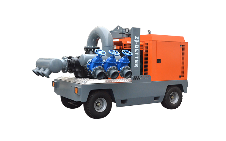
 Sep 14, 2023Introduction of Mobile pump unitBETTER Technology's series of Mobile pump unit appears to have achieved significant success and expertise in urban drainage and mine rescue applications. Here is some key information about these devices:
Purpose: Mobile pump unit are specialized equipment designed for rapid drainage, particularly suited for urban drainage and emergency rescue missions. They boast strong maneuverability, enabling quick responses to reach areas requiring drainage. They can swiftly remove accumulated water, reducing flood risks and supporting rescue efforts.
Water Storage Capacity: BETTER Technology's Mobile pump unit offer substantial water storage capacity, with a maximum of 4,000 cubic meters. This means they can handle large-scale water drainage tasks. Furthermore, there are plans for the development of even higher-capacity equipment, with storage capacities ranging from 5,000 to 10,000 cubic meters. This will further enhance the equipment's performance and value.
Collaboration and Training: BETTER Technology collaborates with Jiangsu University for joint research and development of new drainage equipment, which is expected to enhance product quality. Additionally, they have partnered with the Zhejiang Emergency Management Bureau to establish a rescue team. This team includes three vehicles and dozens of trained personnel who are proficient in operating drainage pump trucks, ensuring these devices can maximize their impact in daily emergency rescue and disaster relief tasks.
In summary, BETTER Technology's series of Mobile pump unit has achieved notable progress in the fields of drainage and rescue. Through ongoing research and development efforts and collaborations, they are continually improving equipment performance to better serve flood prevention and disaster relief efforts in the community.View details -
 Sep 13, 2023BETTER TECHNOLOGY GROU—Professional fire pump manufacturerBETTER TECHNOLOGY GROUP CO., LTD. in the field of firefighting pumps in emergency scenarios seems to be a highly focused enterprise on high-quality, internationally certified products. Here is some important information about Bed Technology in the context of firefighting pumps in emergency scenarios:
UL and FM Certification: UL and FM certifications are the most authoritative global standards for firefighting pumps. UL is the largest product safety testing and certification organization in the United States, while FM is the largest risk insurer. Both certifications impose strict requirements on product safety and performance. FM certification is particularly significant in the industrial product sector, and BETTER TECHNOLOGY GROUP appears to be dedicated to achieving this certification.
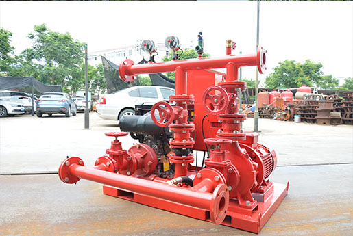
Product Structure: The structure of firefighting pumps primarily consists of a water pump, diesel engine or motor, and control cabinet, with only 13 global manufacturers in this category. Globally, there are just 23 manufacturers with motor certification and slightly over 20 manufacturers with UL and FM certifications combined. There are only around 70 manufacturers worldwide meeting all four certification criteria, and BETTER TECHNOLOGY GROUP is among the fewer than four companies accomplishing this feat. This underscores BETTER TECHNOLOGY GROUP's professionalism and outstanding performance in this field.
Multiple Certifications: Firefighting pump manufacturers must undergo multiple certifications to ensure the quality and performance of their products. Globally, fewer than four companies are capable of simultaneously meeting four certifications, highlighting BETTER TECHNOLOGY GROUP's expertise and excellence in this domain.
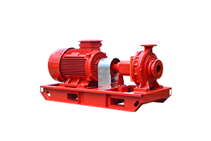
Product Range: BETTER TECHNOLOGY GROUP focuses on the research and production of high-end firepump products, including electric fire pumps, diesel engine fire pumps, jockey pumps, automated control cabinets, and sensors. This means they provide comprehensive firefighting pump system solutions to meet the needs of various emergency scenarios.
Leadership Team: The company's founder, Wei Hua Luo, has nearly 20 years of experience in the firefighting pump industry. He has personally been involved in product certifications and has been instrumental in driving domestic firefighting pumps to meet international standards. He is also actively engaged in firefighting pump installation, maintenance, and industry standard development, demonstrating a long-term commitment to and deep knowledge of the industry.
In summary, BETTER TECHNOLOGY GROUP appears to be a specialized manufacturer of high-quality, certified firefighting pump systems for emergency scenarios. Their product range encompasses several critical components to ensure reliable water supply and control during fire emergencies. Furthermore, their leadership team boasts extensive experience in the field, with a particular focus on advancing the domestic firefighting pump industry to international standards.View details