.png)
.png)
.png)
-
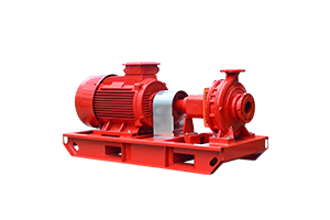
 Nov 09, 2023Installation of diesel engine fire pumpThe installation of a diesel engine fire pump is a critical component of a fire protection system, and it must be done in accordance with local building codes, industry standards, and the manufacturer's recommendations. Below are the general steps involved in installing a diesel engine fire pump:
View details -
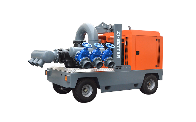
 Nov 07, 2023Driven by technological innovation: our mobile pump trucks lead the industryIt's excellent to hear that your company's mobile pump trucks are leading the industry through technological innovation. Technological advancements can significantly enhance the performance, efficiency, and capabilities of mobile pump trucks, making them more competitive and valuable in various applications.
View details -
 Nov 07, 2023Global Demand Growing: Chinese Manufacturer Supplies Superior Mobile Pump TrucksZJ BETTER TECHNOLOGY GROUP CO., LTD. is proud to announce its position as a leading Chinese manufacturer meeting the increasing global demand for high-quality mobile pump trucks. As the construction, mining, and industrial sectors continue to expand worldwide, our company remains committed to delivering innovative, reliable, and efficient mobile pump trucks to meet the diverse needs of our international clientele.
ZJ BETTER TECHNOLOGY GROUP CO., LTD., based in China, has garnered a strong reputation for manufacturing cutting-edge mobile pump trucks that adhere to the highest industry standards. Our mobile pump units offer numerous advantages that make them the preferred choice for a wide range of applications.View details -
 Nov 06, 2023The importance of mobile pump truck technology to urban constructionMobile pump truck technology plays a crucial role in urban construction for several reasons. Its importance to urban construction projects cannot be overstated, as it offers numerous benefits that enhance efficiency, safety, and cost-effectiveness in this context. Here are some key reasons for the significance of mobile pump trucks in urban construction:
View details -
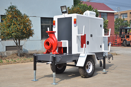 Nov 06, 2023Learn about the advantages and uses of mobile pump trucksMobile pump trucks, also known as mobile pump units or mobile pumping systems, are versatile machines equipped with pumps and various components that can be easily transported to different locations. They offer several advantages and have a wide range of uses in various industries. Here are some of the advantages and common uses of mobile pump trucks:
View details -
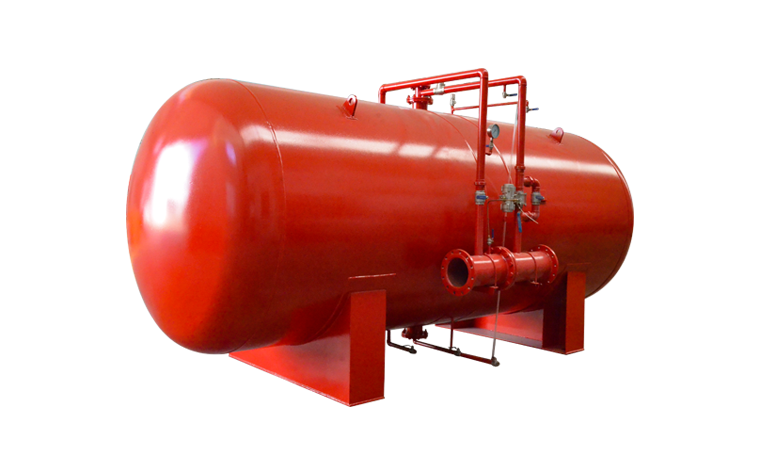
 Nov 03, 2023Fire Pumps and Community Safety: The Importance of Developing Fire AwarenessFire pumps play a crucial role in ensuring community safety by providing an essential resource for firefighting. Alongside this important equipment, developing fire awareness within a community is equally vital for preventing and mitigating fire-related emergencies. Let's explore the significance of both fire pumps and fire awareness in enhancing community safety.
View details